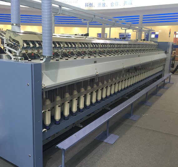
Introduction: Why Is Cotton Yarn Strength Variation Important?
In cotton spinning, yarn breakage occurs when the tension applied to the yarn exceeds its actual breaking strength. Therefore, improving the minimum yarn strength and reducing the coefficient of variation (CV) of yarn strength are essential for minimizing end breaks and maintaining consistent yarn quality.
Yarn strength is not determined by the spinning frame alone. It is influenced by the quality of the sliver, fiber alignment, drafting stability, roving structure, twist distribution, and the operating condition of the machinery throughout the spinning process.
Among these factors, the drawing and roving processes play a particularly important role. Irregularities introduced during these stages may be amplified by subsequent drafting, resulting in long thick places, thin places, uneven yarn strength, and weak sections that are more likely to break during spinning or downstream processing.
For spinning mills seeking to improve production efficiency, reduce end breaks, and maintain consistent yarn quality, systematic control of drawing and roving processes is essential.
This article explains practical methods for reducing cotton yarn strength variation through process optimization, machinery maintenance, and production management.
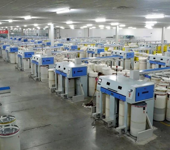
1. How to Reduce Yarn Strength Variation in the Drawing Process
The drawing process improves fiber straightening and parallelization, blends fibers from multiple slivers, and produces a more uniform sliver for the roving frame. Proper drawing-frame operation helps stabilize the subsequent drafting process and improves yarn quality.
However, poor sliver uniformity, inappropriate drafting settings, mechanical irregularities, and inadequate maintenance can introduce defects that become more pronounced during subsequent drafting.
The following five technical measures can help improve drawing performance.
1.1 Optimize the Number of Slivers Fed into the Drawing Frame
For cotton varieties or production batches with significant variations in card sliver quality, increasing the number of slivers combined during drawing may improve blending and reduce sliver irregularity.
For example, under suitable production conditions, a drawing configuration of 6 × 8 can be changed to 8 × 8. The exact configuration should be determined according to the drawing frame’s design, sliver linear density, total draft, and production requirements.
Increasing the number of slivers fed into the drawing frame can improve blending uniformity and reduce the influence of individual sliver variations on the final drawn sliver.
However, the number of doublings should not be increased without reviewing the corresponding drafting parameters. The total draft and the distribution of draft between zones must remain appropriate for the intended output sliver.
1.2 Reduce Drawn Sliver CV and Maintain Consistent Quality
A low coefficient of variation (CV) in drawn sliver linear density is important for producing cotton yarn with consistent strength.
To achieve stable sliver quality, spinning mills should implement the following measures:
- Control card sliver quality: Monitor the uniformity of the input slivers and investigate significant variations between cans or production batches.
- Increase inspection frequency when necessary: For intermediate and final drawing processes, adjust sampling frequency according to production stability and quality requirements.
- Establish a consistent testing schedule: For example, each of three shifts can perform three quality checks per shift, where appropriate for the mill’s quality-control plan.
- Investigate abnormal CV results promptly: Determine whether the problem originates from input sliver variation, damaged top rollers, pressure-loading mechanisms, drafting components, sliver-break monitoring devices, or unstable suction and cleaning systems.
- Maintain stable environmental conditions: Monitor temperature and relative humidity to reduce unnecessary variations in fiber behavior and machine operation.
When the drawn sliver CV exceeds the specified limit, operators should identify the root cause instead of relying solely on repeated adjustments. A structured quality-control process helps prevent recurring defects and maintain stable production.
1.3 Eliminate Long Thin Places Originating in the Drawing Process
Long thin places are particularly harmful because their effects can remain after repeated drafting.
In a typical spinning route, the roving process may apply a draft of approximately 7.5 times, followed by a ring-spinning draft of approximately 40 times. The combined draft is therefore about 300 times.
These values are illustrative and vary according to the spinning system, yarn count, and process design.
If a long thin place is introduced during drawing, subsequent drafting may amplify the irregularity rather than eliminate it. The resulting yarn can contain a locally reduced fiber mass and lower breaking strength.
For this reason, the drawing process should prioritize eliminating long thin places before focusing exclusively on reducing overall sliver CV.
Key areas to inspect include:
- Drawing-frame process design and draft distribution.
- Top roller condition and pressure-loading performance.
- Roller spacing and drafting-system alignment.
- Sliver feeding and guiding arrangements.
- Machine cleanliness and operating discipline.
- Abnormal sliver tension, breakage, or feeding conditions.
A sliver can have an acceptable average CV while still containing isolated defects that create weak yarn sections. Both overall uniformity and localized irregularities must therefore be controlled.
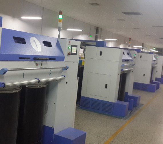
1.4 Optimize Draft Distribution and Fiber Control
Appropriate drafting settings help improve fiber straightening, parallelization, and control within the drafting zone.
As a practical starting point, the following configurations may be considered for suitable drawing-frame applications:
- First drawing passage: Approximately 1.75 times back-zone draft, with front-zone draft within 3.5 times.
- Final drawing passage: Approximately 1.25 times back-zone draft, with front-zone draft around 6.5–7 times.
These are reference values rather than universal settings. Actual parameters must be selected according to machine design, fiber characteristics, sliver specifications, and the required production quality.
The relationship between drafting force and roller gripping force is especially important. The gripping force must provide sufficient control over the fibers to prevent uncontrolled movement through the drafting zone.
If input sliver properties fluctuate, long thin places or thick places may appear in the resulting yarn. Increasing back-zone draft or roller spacing may sometimes reduce drafting force, but these adjustments should not be treated as universal solutions.
Where machine design permits, improving effective fiber gripping and stabilizing roller pressure may provide a more direct solution. Any adjustment should be verified through sliver evenness testing and subsequent yarn quality measurements.
1.5 Eliminate Mechanical Waves in the Drawing Process
Mechanical waves are periodic variations in sliver linear density caused by mechanical irregularities in the drafting or feeding system.
They may not always produce a significant deterioration in the overall yarn evenness CV. However, subsequent high-draft processes can transform these periodic variations into long thick and thin places.
When a low-mass yarn section coincides with a thin place, the resulting yarn may have significantly reduced local strength. This creates a weak point that increases the risk of end breaks.
Spinning mills should therefore regularly monitor drawing-frame output for periodic irregularities and identify their mechanical sources.
Potential causes include roller eccentricity, worn bearings, damaged drafting components, improper roller pressure, and other machine-related defects. Timely maintenance and accurate mechanical adjustment are essential for eliminating these problems.
2. Drawing-Frame Management Measures for Consistent Yarn Quality
In addition to process optimization, effective production management is necessary to maintain stable drawing-frame performance.
2.1 Check Sliver-Break and Sliver-Missing Stop-Motion Devices
The sensitivity of sliver-break and sliver-missing detection devices should be checked and calibrated periodically.
If an operator discovers that a device fails to respond reliably, maintenance should be arranged promptly. Missing or improperly fed slivers can cause substantial changes in the number of slivers entering the drafting system, creating serious linear-density variations.
Reliable stop-motion devices help prevent defects from continuing through the production line.
2.2 Improve Operator Skills and Prevent Improper Sliver Feeding
Operators should follow standardized operating procedures and maintain consistent handling practices.
Particular attention should be paid to:
- Avoiding improper sliver piecing and overlapping.
- Preventing slivers from becoming crossed or tangled during feeding.
- Removing defective output sliver sections.
- Keeping the machine and surrounding area clean.
- Preventing fly and other contaminants from entering the sliver.
- Ensuring that sliver cans and feeding arrangements remain in good operating condition.
These measures help reduce avoidable irregularities and support stable production.
2.3 Monitor Sliver Evenness Across All Machines
Where production and testing resources permit, the CV of drawn sliver evenness should be measured daily or each shift across all relevant machines.
Machines showing abnormal CV values or mechanical-wave patterns should be inspected and repaired promptly.
If the same defect repeatedly appears on a particular machine, spindle position, or component, the mill should investigate the underlying mechanical condition and process settings rather than repeatedly correcting the output alone.
Trend-based quality monitoring helps identify developing problems before they affect a large volume of yarn.
2.4 Protect Top Rollers and Drafting Components
Top rollers are critical components in the drafting system. Scratches, deformation, contamination, and bearing problems can affect fiber control and drafting stability.
Operators should avoid damaging roller surfaces with knives or other tools during cleaning and troubleshooting.
Designated maintenance personnel should regularly inspect roller surfaces, bearings, and operating conditions. Where compatible with the roller material and equipment manufacturer’s instructions, an appropriate cleaning agent can be used to remove accumulated wax, oil, and other contaminants.
Proper maintenance helps preserve roller performance, stabilize drafting, and reduce the risk of uneven sliver formation.
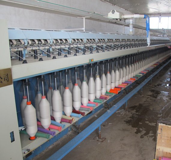
3. How to Reduce Yarn Strength Variation in the Roving Process
The roving process directly influences ring-spinning performance. A stable roving structure provides better fiber control during final drafting and helps improve yarn evenness, strength consistency, and spinning efficiency.
The main quality indicators include roving evenness, linear-density variation, twist, elongation, and consistency between spindles and bobbins.
Three key technical measures should be considered.
3.1 Optimize Roving Twist for Stable Ring Spinning
Roving twist has a close relationship with yarn quality and the drafting settings used in the ring-spinning process.
Increasing the roving twist factor appropriately can improve fiber cohesion and help control fibers in the ring-spinning drafting zone. It can also reduce accidental drafting during roving unwinding, which may otherwise create thin places.
However, excessive roving twist can make the roving difficult to draft. This may lead to drafting irregularities, increased thick and thin places, poor fiber control, and higher end-break rates.
Roving twist should therefore be selected according to several factors:
- Roving linear density.
- Fiber length, fineness, and other fiber properties.
- Required yarn count and yarn quality.
- Drafting-system design and mechanical condition of the ring frame.
- Draft distribution and roller settings.
- Required balance between roving stability and draftability.
Rather than increasing twist indiscriminately, mills should conduct controlled trials and evaluate roving evenness, ring-frame end breaks, yarn strength, and yarn CV together.
3.2 Monitor and Eliminate Mechanical Waves in the Roving Frame
Mechanical waves in roving can produce periodic linear-density variations that remain visible in the final yarn after high drafting.
Regular testing is important for identifying affected machines and individual spindle positions. Equipment with severe mechanical irregularities should be inspected and repaired promptly.
The condition of the false-twist device, roving guides, condensers, and other fiber-collecting components also requires attention. Poor surface finish, damaged components, or an unsuitable roving passage can affect fiber arrangement and reduce the stability of subsequent drafting.
Because roving has relatively low twist, fiber cohesion may be insufficient to compensate for poor handling or an unstable roving structure. Correctly functioning false-twist devices and smooth, properly maintained fiber passages are therefore important for reliable production.
3.3 Control Roving Elongation and Prevent Accidental Drafting
Roving elongation affects roving evenness and linear-density variation. Differences in elongation between front and rear rows, large and small bobbins, or individual spindles can also contribute to variations in final yarn evenness and strength.
Spinning mills should monitor roving elongation and reduce unnecessary variation through appropriate process settings and equipment maintenance.
Additional attention should be given to the following points:
- Minimize accidental drafting of drawn sliver while it travels through overhead creels and guide systems.
- Ensure that roving-frame anti-thin-place devices operate correctly.
- Monitor roving quality during machine starting, stopping, and restarting.
- Maintain consistent operating conditions between front and rear rows.
- Investigate differences between individual spindle positions.
- Check that roving tension and winding conditions remain stable.
Thin places generated during machine start-up or stopping can become weak sections in the final yarn. Effective monitoring and correct operation of protective devices help reduce these defects and improve spinning stability.
4. Establish a Systematic Yarn Quality Improvement Program
Reducing cotton yarn strength variation requires coordinated control across the drawing, roving, and ring-spinning processes. Adjusting a single machine parameter rarely solves every quality problem.
A systematic improvement program should include the following steps.
Step 1: Establish a quality baseline. Record drawn sliver CV, roving CV, yarn strength, yarn strength CV, yarn evenness, and end-break rates.
Step 2: Identify the source of variation. Determine whether weak yarn sections originate from input material differences, drafting instability, mechanical waves, roller conditions, roving twist, or accidental drafting.
Step 3: Optimize process settings. Adjust doubling, draft distribution, roller pressure, roller spacing, and roving twist according to the equipment design and production requirements.
Step 4: Strengthen preventive maintenance. Inspect rollers, bearings, drafting components, stop-motion devices, false-twist devices, and fiber-guiding components on a defined schedule.
Step 5: Verify improvements through testing. Compare quality data before and after adjustments. Confirm that improvements in sliver and roving uniformity translate into more consistent yarn strength and fewer end breaks.
Step 6: Standardize successful practices. Document proven settings, inspection requirements, and operating procedures so that improvements can be maintained across shifts and production batches.
By combining process optimization with routine testing and preventive maintenance, spinning mills can reduce avoidable yarn defects, improve production continuity, and maintain more consistent yarn quality.
Conclusion: Improve Yarn Strength Stability Through Better Process Control
Cotton yarn strength variation is a system-level problem that requires attention throughout the spinning process. The drawing frame helps establish fiber alignment and sliver uniformity, while the roving frame influences fiber cohesion, drafting stability, and the consistency of the feed supplied to ring spinning.
Optimizing drawing parameters, eliminating mechanical waves, maintaining roller performance, controlling roving twist, and reducing accidental drafting can all contribute to more stable yarn strength and fewer end breaks.
The most effective solution combines suitable spinning machinery, well-designed process parameters, reliable maintenance, and continuous quality monitoring. Since fiber properties and machine configurations vary between mills, process settings should always be validated against actual production results.
Looking for reliable textile machinery for your spinning mill?
Choosing suitable spinning equipment and maintaining stable process conditions are important steps toward improving yarn quality and production efficiency. Contact our team to learn more about our textile machinery solutions and discuss equipment options for your production requirements.
Contact us today to discuss your spinning process and machinery needs.